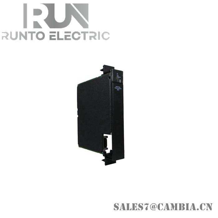
IC697CPU781 GE CPU MODULE
| Brand: | GE Fanuc | Item No: | IC697CPU781 |
| Type: | PLC | Warranty: | 1 year |
| Service: | One Year Warranty | Quality: | 100% New And Origin |
| Delivery Time: | 1-3 Days | Condition: | In Stock |
| Product information: |
IC697CPU781 |
||
NEW AND ORIGIN ITEM IN STOCK
WITH ONE YEAR WARRANTY
Hope anyone enquire from us,pls click this sales7@cambia.cn

► Product Description
The IC697CPU781 is a Programmable Logic Controller CPU that fits into a single rack slot. To communicate with various “smart option” modules, a rack-mounted backplane with several connectors is used. A toggle control switch with three positions or a connected computer with specific software is used to operate this device.
The IC697CPU781 has a 16MHz microprocessor. Boolean functions are calculated every 0.4 microseconds. Up to 8K analog I/O is supported by this device, along with any mixture of 12K inputs and outputs. Several “smart option” modules are supported such as the IC697 series of discrete and analog modules. IC697 LAN modules and bus controllers for IC660 and IC661 modules are also supported.
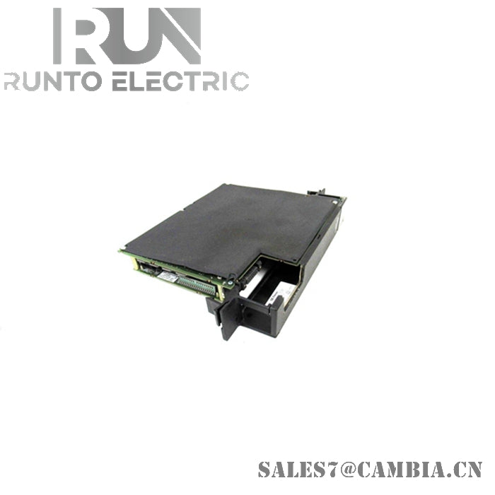
To store user and configuration information, an expansion board is required. This board supplies up to 512 kilobytes of volatile memory sustained by a CMOS battery and up to 256 kilobytes of non-volatile flash memory (NVRAM). The calendar and clock for this device is also sustained by the CMOS battery.
The IC697CPU781 is programmed with software on a connected computer, not DIP switches or jumpers. Special programs running on certain operating systems such as MS-DOS, Windows 95, and Windows NT are used to program this device. A parallel, serial connection to this attached computer is possible, as is an Ethernet connection. An Ethernet connection will require an Ethernet controller or type 2 Ethernet interface to be installed. Options to protect configuration data and settings include a memory protection switch or a password in the programming software.
Follow the device documentation while attempting installation. Do not attempt installation while rack is powered on. Place the device control switch into the stop position. Turn the memory protection switch to the off position. Connect the memory expansion board to the device. Install the CMOS battery into the appropriate slot on the device. Insert the device into the first available rack slot. Turn the power back on.
IC697CPU781 GE CPU MODULE